1 Abstract
This documents how AuxTel mount jitter is impacted by airflow from the fan which ventilates the building, and shows the correlation between mount jitter and accelerometer and anemometer data.
2 First test 22-Feb-22
A ventilation fan was installed in the AuxTel dome to aid with bringing the dome into temperature equilibrium with the outside air. The fan is installed in one of the vent windows on the first floor and blows outward, drawing air into the dome through other openings (other vent windows, the dome slit). After the fan was installed, it was noticed that it was causing degradation to the image quality and mount tracking accuracy. So a series of tests were run to determine the cause. One hypothesis was that the fan was causing vibration of the building, which was being transmitted to the telescope mount. To test this, the fan was ramped up in speed while the other vent windows and the dome slit were closed. The plots below show that in this condition, the fan speed has no impact on the mount tracking errors. So this rules out vibration of the building as the cause of the tracking errors. Also note that the azimuth oscillation seen in these tests was later understood to be due to a phenomenon called “cogging”, which is unrelated to the fan-induced vibrations.
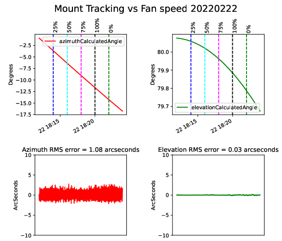
Fan speed has no impact on mount tracking errors with slit closed.

Azimuth oscillations are due to “cogging” and unrelated to fan speed
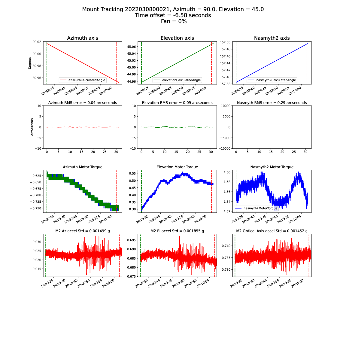
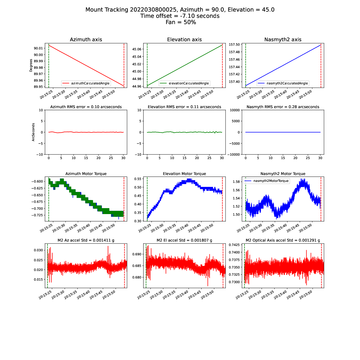
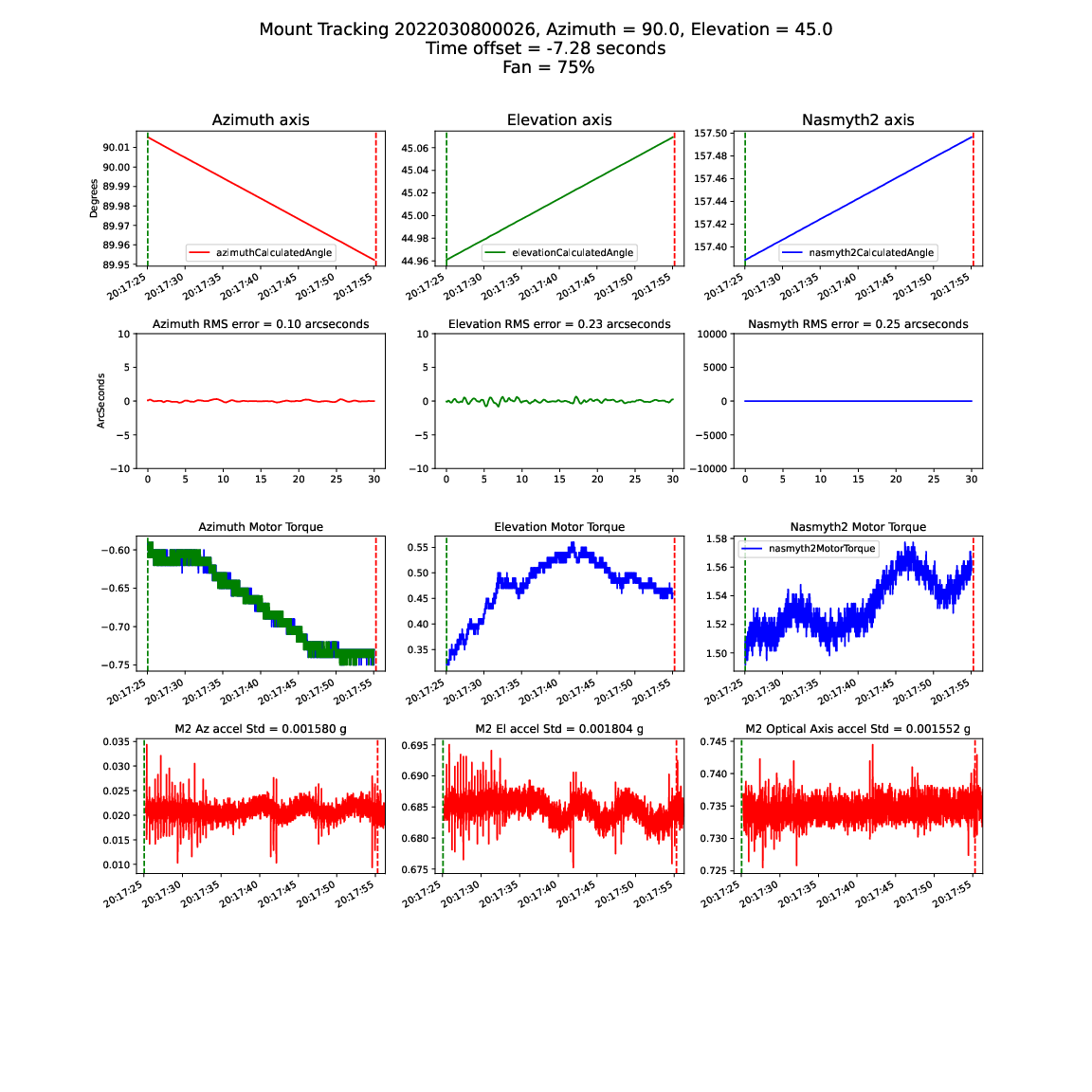
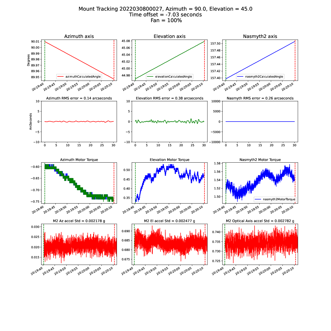
3 Second test 08-Mar-22
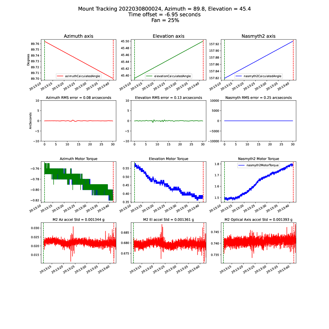
This test was then repeated with the dome slit open. The plots below show the mount tracking error increasing steadily as the fan speed is increased. The conclusion is that the mount tracking errors are caused by turbulent wind buffeting the mount. The elevation mount tracking errors are also very similar to that seen when mount jitter is seen when observing during times of high wind speed.
3.1 Fan speed at 0%
3.2 Fan speed at 25%
3.3 Fan speed at 50%
3.4 Fan speed at 75%
3.5 Fan speed at 100%
3.6 Summary
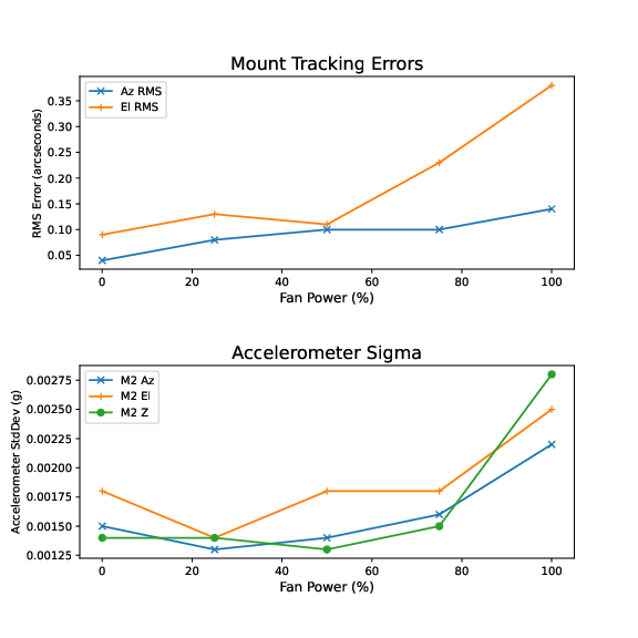
Summary of impact of fan speed on mount tracking errors
3.7 Comarison plot of observing jitter caused by wind shake
An image from AuxTel observing with “mount jitter”, which looks very similar to the fan-induced errors.
4 Third test - 04-Oct-22
The test was repeated on 04-Oct-22. By this time the instrumentation was more sophisticated. A Campbell Scientific 3D sonic anemometer had been introduced to the AuxTel dome, with the data being read into the EFD. Also, the accelerometer data was now being read into the EFD, where a power spectrum of each of the 9 accelerometers is stored every 2 seconds. The wind velocity outside the dome was about 35 km/hr on the day of the test, which may have added noise to the measurements. Because of the wind, the dome slit was only opened to about 50%. The telescope and dome were aligned to point in the direction of the (fixed) 3D anemometer. The figure below shows the setup:
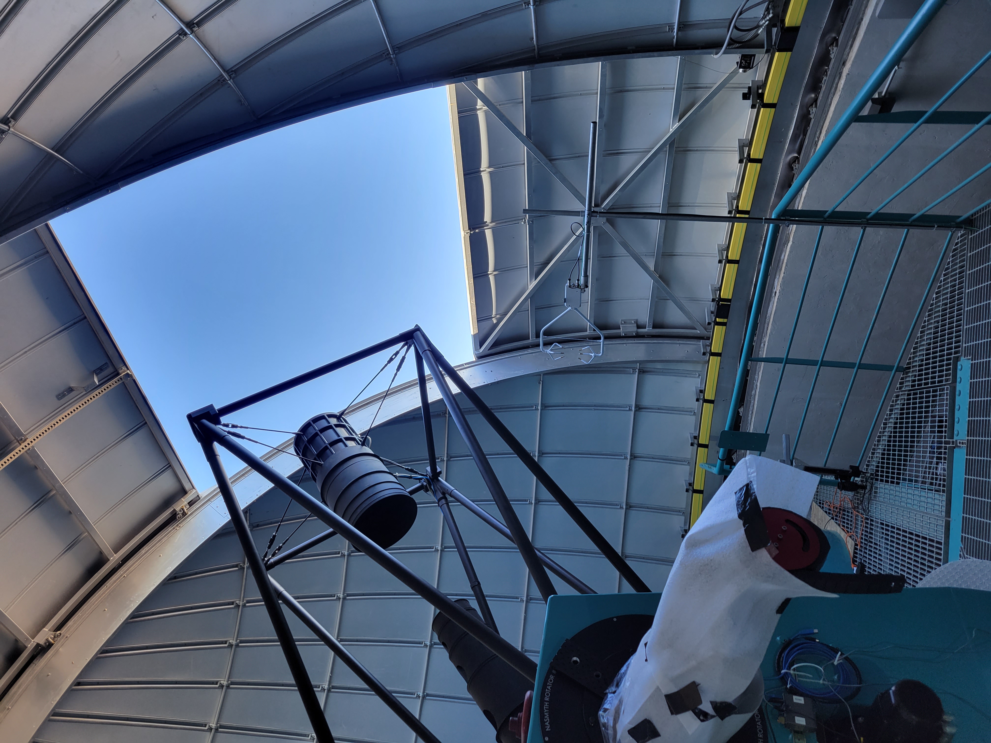
Setup on 04_Oct-22
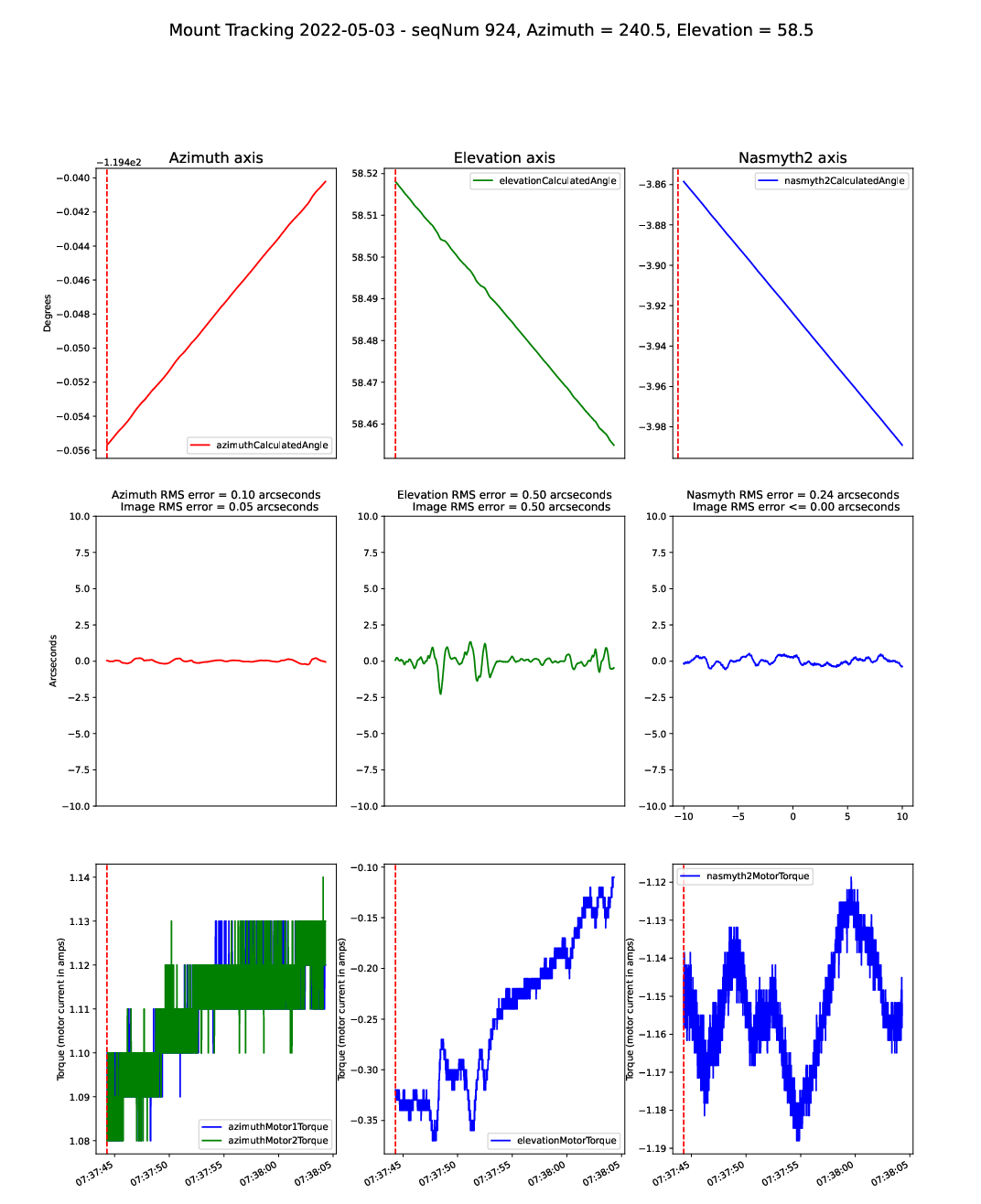
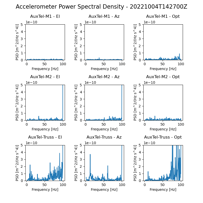
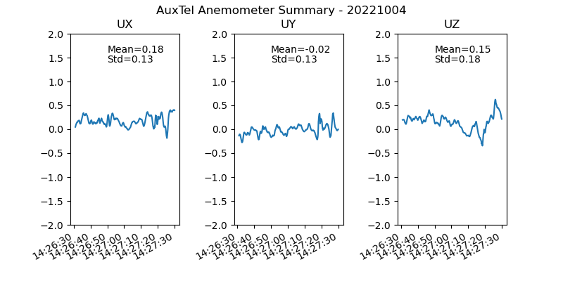
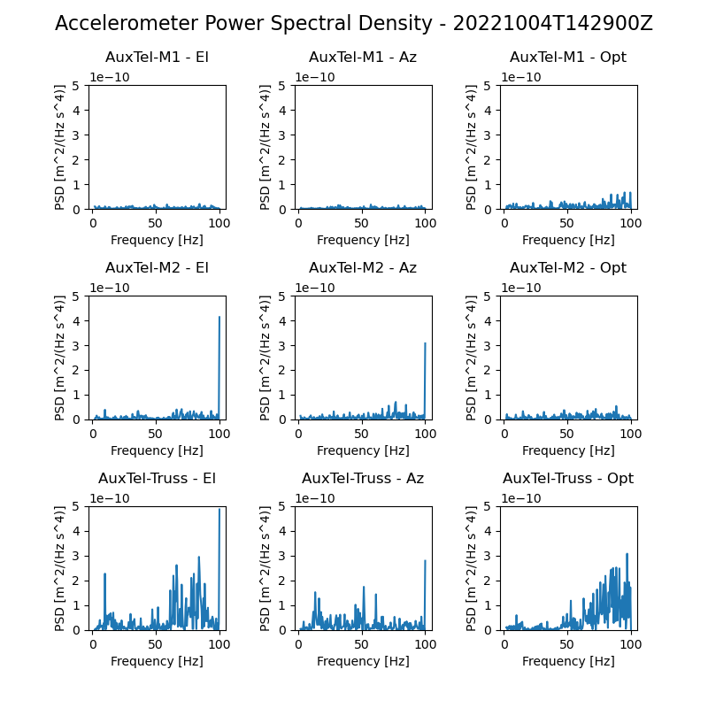
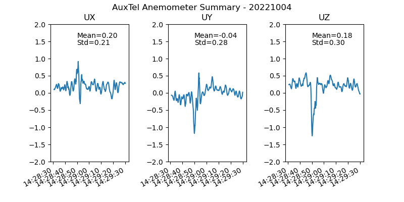
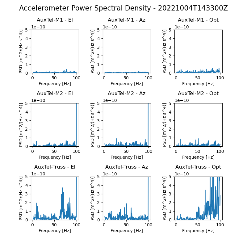
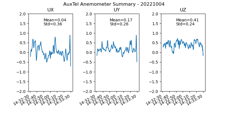
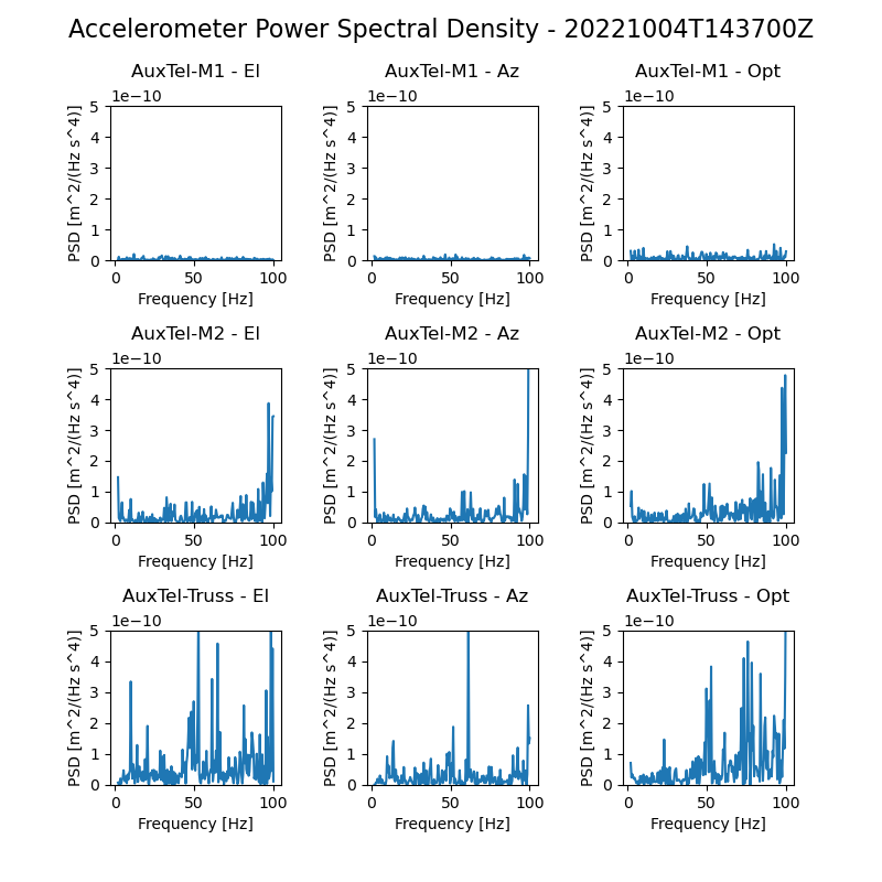
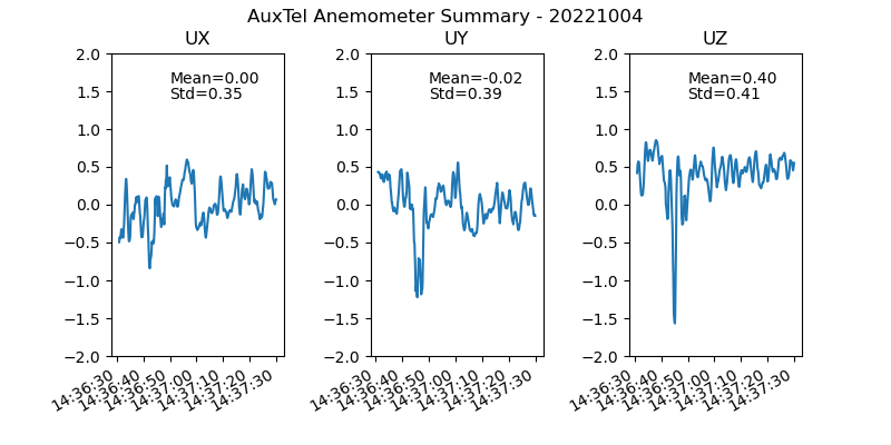
These images show the anemometer readings, the accelerometer readings, and the mount encoder data as the fan speed is ramped up:
4.1 Measurements with Fan Speed at 0.0 Hz

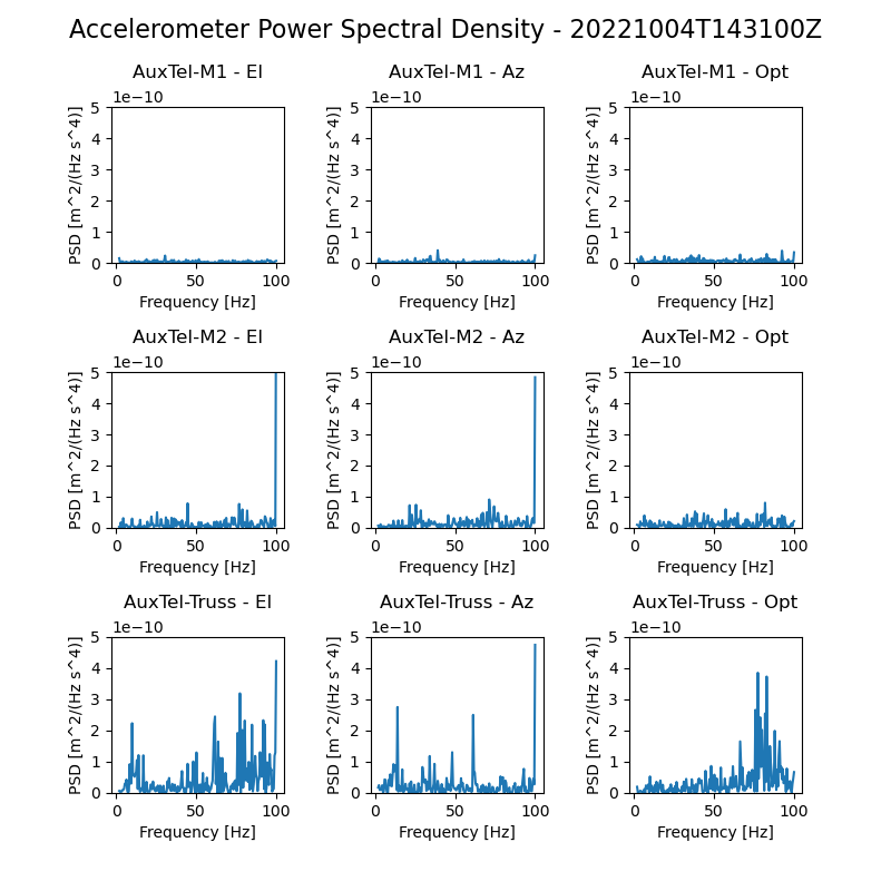
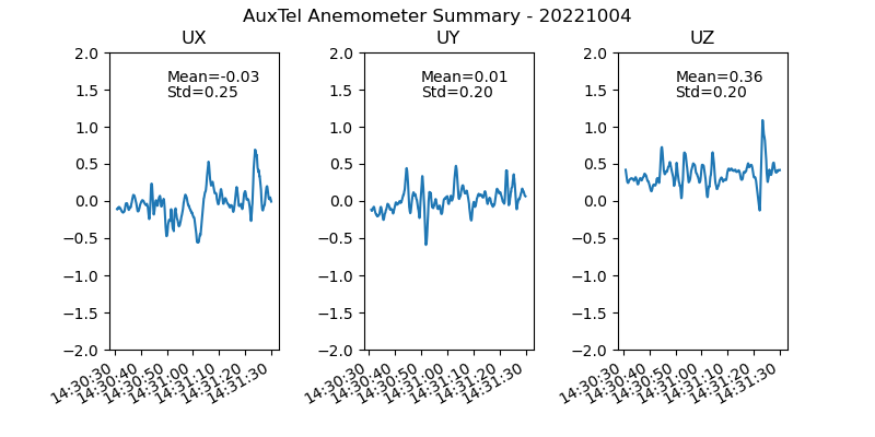
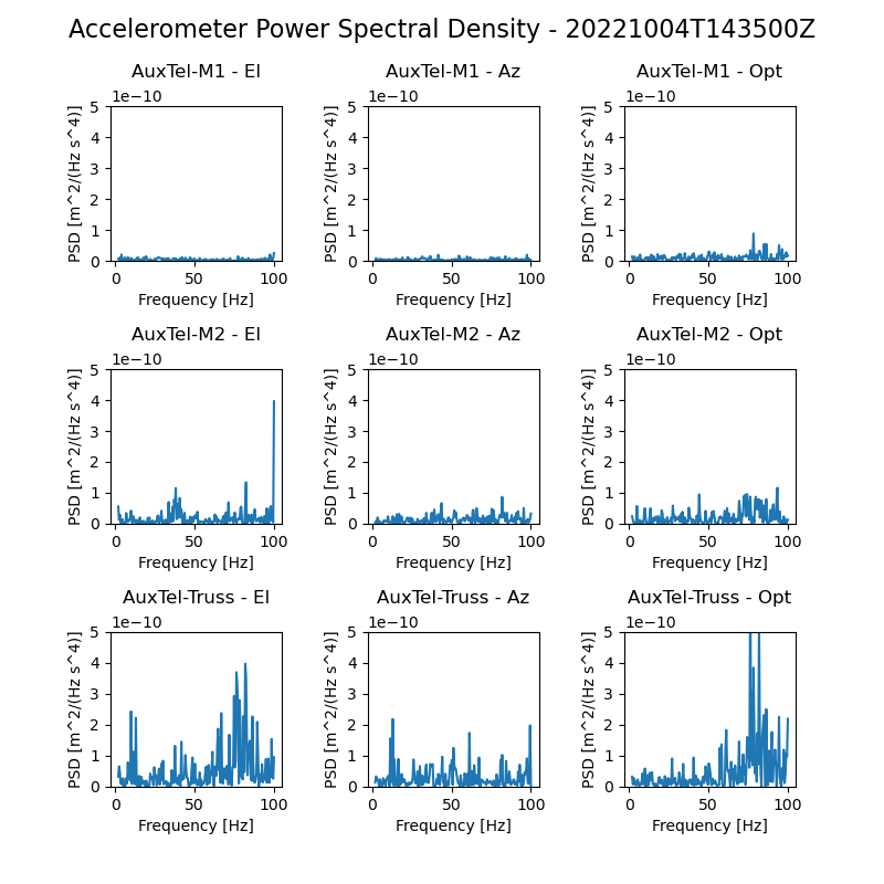
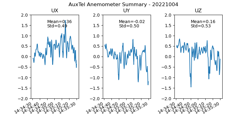
4.2 Measurements with Fan Speed at 10.0 Hz
4.3 Measurements with Fan Speed at 20.0 Hz
4.4 Measurements with Fan Speed at 30.0 Hz
4.5 Measurements with Fan Speed at 40.0 Hz
4.6 Measurements with Fan Speed at 50.0 Hz
4.7 Summary of measurements
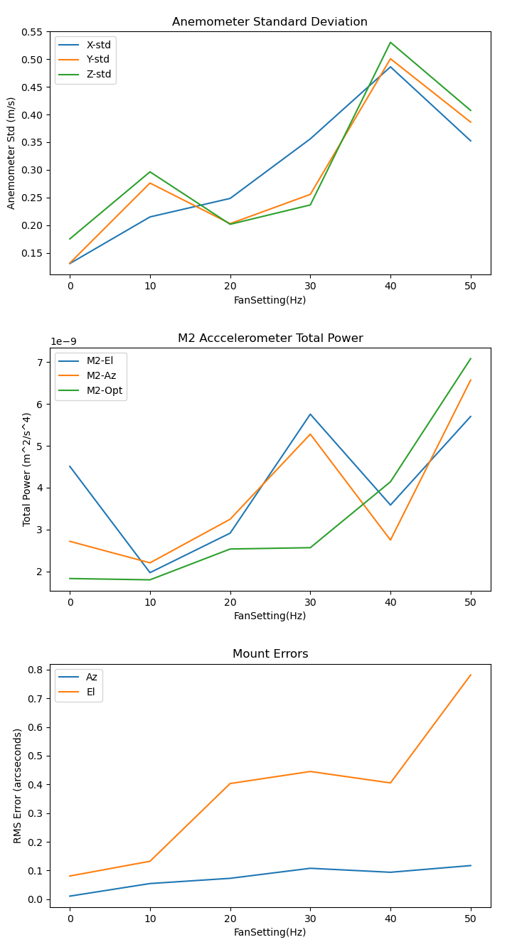
This is a summary of the measurements taken. The anemometer standard deviation, the total accelerometer power, and the mount tracking error all ramp up as the fan speed is increased.
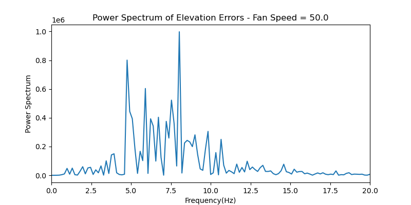
4.8 Power spectrum of elevation errors
Also, I looked at the power spectrum of the elevation mount errors. The power is all under 10 Hz:
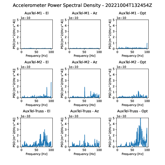
5 Search for understanding of accelerometer PSD peaks
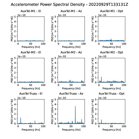
The accelerometer power spectra typically show some peaks. This describes an attempt to understand those peaks. First, below is a quiescent (afternoon, dome closed and empty) power spectrum on 29-Sep-22. The primary peaks are seen around 10 Hz and around 70Hz. What causes those peaks?
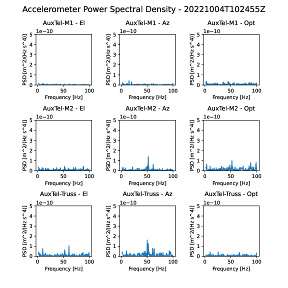
A similar spectrum is seen on 04-Oct-22. There are also peaks at around 50Hz. This could be 50Hz AC pickup, but it only affects some channels.
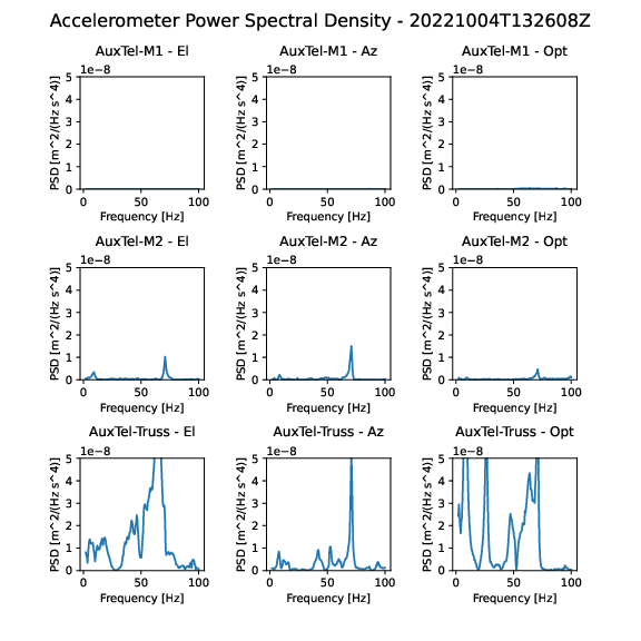
I hypothesized that the higher frequency peak around 70 Hz could be a stretching oscillation along the length of the mount struts. By banging on the end of the strut, I could excite this mode, as shown below. Note the scale has been increased by a factor of 100:
Banging on the side of the strut to excite some kind of bending mode was less successful, and seemed to excite a wide range of frequencies: